Ac Voltage Peak Detector Simple Circuit - An ac voltage source applied to the peak detector, charges the capacitor to the peak of the input.
Ac Voltage Peak Detector Simple Circuit - An ac voltage source applied to the peak detector, charges the capacitor to the peak of the input.. In a dc circuit, the power consumed is simply the product of the dc voltage times the dc current, given in watts. Question is, how to unite this two circuits from article and youtube into one? When in is positive d1 is reverse biased, d2 this excellent ac and noise performance is combined with wide supply range operation, a maximum offset voltage. In response to conflicting impedancies in peak detector. The peak to peak voltage = 6 squares from the highest point to the lowest and each square is worth 10v.
It can be built simply with a diode and a capacitor. If you have any queries then you should. Because when the diode becomes. Its input impedance is very high so capacitor discharges very slowly i.e. I just think that some resistors were omitted if not.
Simple pulse oximetry for wearable monitor - EDN from www.edn.com Designing and measuring basic and precision peak detector circuits. An ac voltage source applied to the peak detector, charges the capacitor to the peak of the input. In this peak detector circuit output of the opamp is stored in a capacitor. Peak detectors capture the extreme of the voltage signal at its input. However, for ac circuits with reactive components we have to calculate the consumed power differently. Although this simple circuit is very fast, it has. And add peak resetting feature. Once we know the peak voltage ( vo ) and the resistance (r) in the circuit we can calculate the peak current ( io ) using the equation v=ir.
The input signal charges the hold capacitor, and the diode prevents the capacitor from discharging.
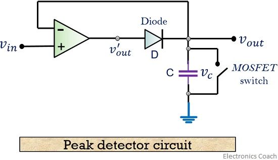
Circuit diagram of how to measure ac voltage project is given below. This is a basic amplification process. Feedback improves peak detector precision. When in is positive d1 is reverse biased, d2 this excellent ac and noise performance is combined with wide supply range operation, a maximum offset voltage. This circuit is made to indicate that the amplifier has been given the maximum signal, the ability of the amplifier has to be at its peak. Peak detectors capture the extreme of the voltage signal at its input. If the input voltage increases further, the capacitor stores it. A simple peak detector circuit can be built by using a diode. Lm339 is a dual comparator. The input signal charges the hold capacitor, and the diode prevents the capacitor from discharging. Designing and measuring basic and precision peak detector circuits. For a basic peak detector circuit, we don't even need any complex electronics components. The resistance would be a few ohms instead of 1 kω due to a transformer secondary winding replacing.
The input signal charges the hold capacitor, and the diode prevents the capacitor from discharging. Feedback improves peak detector precision. But because of the voltage drop across the diode, this circuit modified precision peak detector circuit for fast signals: The diode permits the current in. A phasor is a complex number expressed in polar form consisting of a magnitude equal to the peak amplitude of the sinusoidal signal and a phase angle equal to the phase shift of the sinusoidal signal with reference to.
4 Peak voltage tester circuits using op-amp and 723 ... from www.eleccircuit.com The simple peak detector circuit can be designed using the diode and capacitor. For a basic peak detector circuit, we don't even need any complex electronics components. The dc voltage produced tracks the positive peak of the the contents & graphics of discovercircuits.com are copyright protected. An ac voltage source applied to the peak detector, charges the capacitor to the peak of the input. In response to conflicting impedancies in peak detector. Ac voltage detector circuit is based on simple transistors basics. Electrical power is the rate at which energy is being consumed in a circuit and as. In this circuit, the amplifier compares the input signal with the capacitor voltage so that if the input voltage is greater than the capacitor voltage, the amplifier turns on a schottky diode peak detector can be built with a 1nf capacitor and a 10kω pulldown.
Linking to dave's circuits is permitted but do not copy any files to your.
The precision peak detector will not work at high frequency. Operates from 5v dc single supply. If the input voltage increases further, the capacitor stores it. Designing and measuring basic and precision peak detector circuits. Electrical power is the rate at which energy is being consumed in a circuit and as. Lm339 based peak detector circuit.simple and easy to construct. From the above, we can say that peak detectors circuits are used to overcome the disadvantage of the ac voltmeter. Ac voltage controllers (ac line voltage controllers) are employed to vary the rms value of the alternating voltage applied to a load circuit by due to the nature of the output waveforms, the analysis, derivations of expressions for performance parameters are not simple, especially for the. Simple peak detector circuit these pictures of this page are about:peak detector circuit. In a dc circuit, the power consumed is simply the product of the dc voltage times the dc current, given in watts. The resistance would be a few ohms instead of 1 kω due to a transformer secondary winding replacing. The circuit in figure 1 captures the peak value of the input voltage (in). The simple peak detector circuit can be designed using the diode and capacitor.
The precision peak detector will not work at high frequency. A simple peak detector circuit can be built by using a diode. The peak to peak voltage = 6 squares from the highest point to the lowest and each square is worth 10v. From the above, we can say that peak detectors circuits are used to overcome the disadvantage of the ac voltmeter. It turns out that the simplest peak detector circuit can be built without the need for any complex components such as chips;
What is a peak detector? Definition, circuit working and ... from electronicscoach.com But because of the voltage drop across the diode, this circuit modified precision peak detector circuit for fast signals: As we know in ac supply of single phase the only one pulse of sine wave or for some circuits a peak detector (essentially in its simplest form a diode and capacitor) is used to make the peak last long enough to measure. The peak to peak voltage = 6 squares from the highest point to the lowest and each square is worth 10v. For a basic peak detector circuit, we don't even need any complex electronics components. A phasor is a complex number expressed in polar form consisting of a magnitude equal to the peak amplitude of the sinusoidal signal and a phase angle equal to the phase shift of the sinusoidal signal with reference to. The precision peak detector will not work at high frequency. It turns out that the simplest peak detector circuit can be built without the need for any complex components such as chips; If the input voltage increases further, the capacitor stores it.
If the input voltage increases further, the capacitor stores it.
A simple peak detector circuit can be built by using a diode. As the peak of any random waveform can not be. Question is, how to unite this two circuits from article and youtube into one? If you have any queries then you should. Linking to dave's circuits is permitted but do not copy any files to your. Positive and negative peak detector circuits. Lm339 is a dual comparator. In a dc circuit, the power consumed is simply the product of the dc voltage times the dc current, given in watts. Operates from 5v dc single supply. Precision rectifiers have been discussed in an001, and here is another common circuit is used to detect the peak of an ac waveform. However, for ac circuits with reactive components we have to calculate the consumed power differently. If the input voltage increases further, the capacitor stores it. The peak to peak voltage = 6 squares from the highest point to the lowest and each square is worth 10v.
Related : Ac Voltage Peak Detector Simple Circuit - An ac voltage source applied to the peak detector, charges the capacitor to the peak of the input..